PWM and CAN
PWM
- Stands for Pulse Width Modulation.
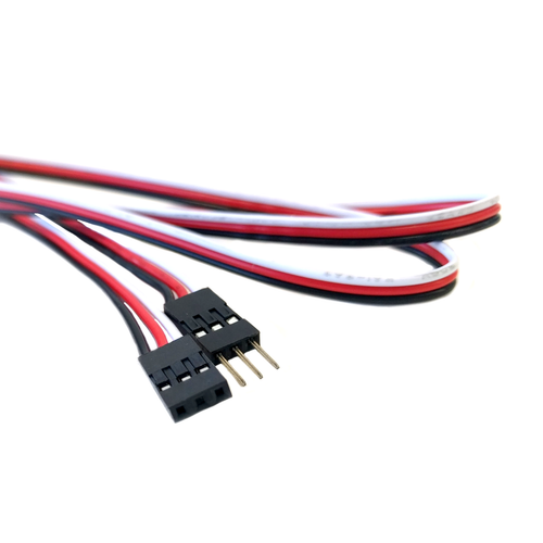
- Uses three individual wires colored white, red, and black (signal, power, and ground)
- Provided an analog
- Consider an anlog signal to be like a knob, while digital signals are like a switch. The knob could be between fully off and on, while the switch can only be on and off. So PWM is similar to a knob, we can give a variable signal.
- Some motor controllers use PWM, but genuinely don't worry about it, because we will just use CAN.
- Each device wired through PWM needs to be connected to a corresponding port on the PWM section of the RoboRIO.

CAN (Controller Area Network)
- Is a method of Serial communication
- Like the I2C and the SPI bus in that regard
- Serial communication really just means that both devices can "talk" to each other
- This is the reason we use CAN for motor controllers, because that way we can get information from the motor controller, like what is the motor's actual RPM, and stuff like that.
- We use yellow and green wire for CAN
- Connect Yellow to Yellow and Green to Green
- We will start it at the PDH, and it will terminate at the roboRIO.
- CAN Bus bar
- Using the bus bar serves to simplify the wire management; if one node fails, the signal will still be able to partially function and send signals to the next node.
- Daisy Chaining
- This is how we connect all CAN devices.
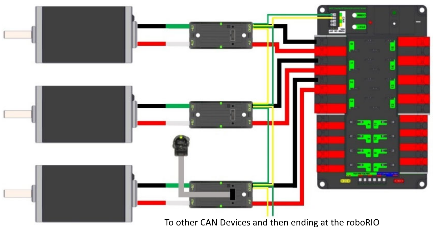
- The CAN chain will start at the PDH, and it will go to the first device, for example the PCM, and then from the PCM it will go to a talon SRX, and so on and so forth, till it terminates at the roboRIO
Daisy chaining between motors would look like this: 
Other Wiring Things to know
Velcro Brackets
Velcro brackets are 3d printed brackets through which you can thread a piece of velcro and bundle and secure wires.
Zipties
We used zip ties in the 2025 season to secure motor controllers and to ensure that the wires don’t get caught up in the wheels.
WAGOs
We used WAGOs to connect wires to each other. They are a replacement for Andersons. We made this switch because Andersons restricted our ability to quickly shift wires around and make changes to the design.
Wire labels
In the 2025 season we used wire labels (stickers with numbers on them) to label a group of wires and its respective motor controller for better wire management. It helped to quickly locate which wires go where.